
MONITORING BASIC PARAMETERS TO DIAGNOSE PACKAGED TREATMENT UNIT
Richard Ross, PE, Regional Product Manager, WesTech Engineering Inc.
Miles Snyder, Application Engineer, WesTech Engineering Inc.
David Lucey, Technical Service Manager, WesTech Engineering Inc.
This is a supplement to an article published in the Fall/Winter 2017 issue of NewsLeaks, titled “Monitoring Basic Parameters Can Optimize Package Plant Operation,” which detailed a method to look at head-loss and solids removal in a package plant to efficiently operate a package plant. Since then several plants have been visited and, in one instance, this method helped identify and diagnose a package plant that wasn’t performing as well as others.
Recapping, a common package plant configuration is clarification followed by filtration. Chemicals such as a coagulant and one or more polymers are used to make contaminants insoluble and cause them to stick together and form larger particles so that they can be captured in the clarifier or filter. Basic instrumentation includes devices such as: influent and effluent turbidimeters, differential pressure transducers, or switches and gauges.
There are three parameters (indicated by circles in the diagram, right) that can be monitored to show how well the process is working and will help to optimize the overall package plant. (1) The Influent turbidity is one parameter measured and typically higher than raw water turbidity as it contains the turbidity of the raw water, chemistry additions, and any coagulated particles, and can also be referred to as coagulated turbidity. Another (2) is settled water turbidity or inter-stage turbidity, which is the turbidity out of the clarifier
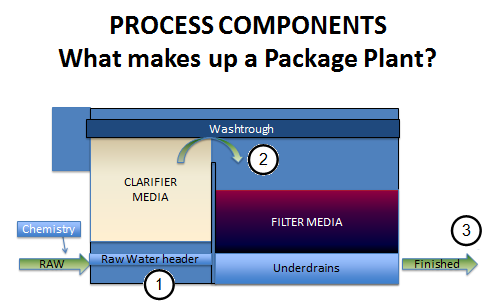
or onto the filter. It is not necessary to continuously record the inter-stage turbidity. Of course, filtered effluent water turbidity (3) is needed, as well as a headloss across the clarifier and filter.
During a recent site visit to a WTP in the Northeast US, there were three similar packaged treatment units but one was not performing the same as the other two. The operations staff couldn’t understand why as the three units were the same, received the same chemistry, and received the same flow.
More specifically: One Microfloc Trident TR-210A system (consisting of 2 Stainless Steel units) was installed March 1992. A third unit was installed in 2015. These package plants utilize a buoyant-media adsorption clarifier (AC), followed by a mixed media gravity filter.
Process Flow Scheme
The source water comes from the local stream and is pumped directly to the plant. Inlet turbidities range from 0.089 – 1.5 NTU and they have seen only a few spikes not much greater than 1.5 NTU. Color ranges from 7-30 apparent color units. Raw water organics range from 3.8 – 4.5 mg/L, raw water alkalinity is about 3 mg/L, pH 6.5-6.8 with negligible amounts of manganese. The inlet water temperature runs between 3.9 and 21 deg C.
The only chemical fed prior to the treatment units is a Nalcolyte 8105. It is a polyamine used as a coagulant and flocculant. It is fed prior to the static mixer. Dose rate ranged from 0.5 – 10.55 mg/L. Chorine is used for post treatment disinfection. No post treatment pH adjustment, corrosion control or fluoride is used. The chemical feed is manually-controlled based upon flow rate.
Operation
The plant operates 7 days a week, 12-18 hours per day and 365 days a year. The plant produces 45,000 – 80,000 gpd which is seasonally adjusted. Two units are run at a time. Nominal flow through each tank is 350 gpm or 0.5 MGD. Each clarifier flushes and filter backwashes every 1800 minutes (30 hours), sequentially, typically on time, but also on high headloss. Filter-to-waste is run for 16 minutes. Flush and backwash waste is sent to sewer.
Diagnosis
We discussed how to evaluate each unit’s performance and suggested taking a turbidity sample from the raw water, water under the clarifier and on top of the filter to determine the solids removal for each step. Water samples were taken from the #2 unit and we found the following:
| Raw | Under AC | Over AC | Finished |
| 0.357 NTU | 5.03 NTU | 0.357 NTU | 0.067 NTU |
From this we saw 92% reduction of solids from the AC and 81.3% solids removed across the filter. We noted that this was pretty good and showed that this unit was functioning well.
While speaking about the units, the plant personnel indicated that he first unit didn’t perform as well as the other two and they were not sure why the effluent quality was different. Water samples taken from the #1 unit and we found the following:
| Raw | Under AC | Over AC | Finished |
| 0.357 NTU | 0.663 NTU | 0.330 NTU | 0.095 NTU |
From this we saw only a 50% reduction of solids from the AC and 71% solids removed across the filter. We had now quantified the relative performance and it was confirmed that something was indeed wrong with the #1 unit.
Fortunately, the #1 unit was nearly ready for a flush and backwash and we would be able to observe and take samples. We wanted to do a clarifier and filter wash out curve so we could see how well they were being cleaned. Everyone agreed and we set up a timer, 15 cups and a dipper to collect samples.
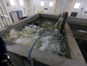
During the AC flush, we could see that the air scour was not evenly distributed across the basin. The raw water line was below the far side and inlet air was in the foreground of the photo.
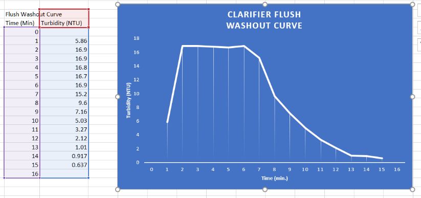
For the AC flush washout curve, we found that it appeared to be normal. It was not spending too much time with excessive rinsing and was long enough to clean the bed properly. The raw water used to flush the clarifier has a low turbidity of ~0.4 and they cannot get any lower than that.
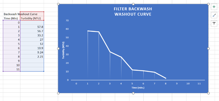
The filter backwash washout curve is shown on the right. Again, the filter media is being sufficiently cleaned and the backwash process is certainly not running too long, i.e. they are not wasting water. The filter-to-waste step runs for about 15 mins before going on line.
Once the blower stopped for the clarifier, the filter water level was lowered and the blower started backwashing the filter, even while the clarifier was releveling and rinsing. The distribution of air looked normal and we didn’t see any media craters or cracks.
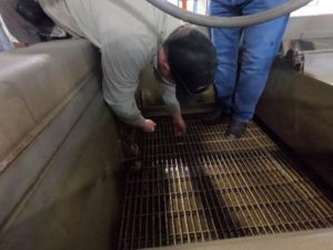
We then discussed how the AC media depth can be checked with a wire. Using a 5’ piece of 14-gage wire, with a 90 deg bend 2” from the bottom, we could check the depth of the buoyant clarifier media. The water level in the AC compartment was lowered and the operator worked at getting the wire through the screen. You could see and feel the sharp edges of the AC media poking through the screen.
Problem Found
Checking the media on one side of the trough it measured about 48 inches deep and on the other side it was less than 30 inches. The correct depth of the media was 48 inches. This indicated that a lot of the media was missing and had shifted to one side. This was the reason this unit didn’t perform as well as the others.
Additional clarifier media was needed.
Using these techniques, one could quickly figure out how the units were performing.
- By monitoring the basic parameters of turbidity, calculating the percentage of solids removed, one could compare the performance in solids removal from one unit to another and found that one was not retaining the solids as well as the others.
- With this information and further investigation, a clarifier flush was initiated, observed and a clarifier and filter wash-out curve was created.
- Then the clarifier media depth was checked and determined the depth of buoyant clarifier media was not correct.
- Some quick and basic measurements can help quickly identify operational issues.
About the Authors
Richard Ross, P.E., is a Regional Product Manager, for WesTech Engineering, Inc. in Natural Bridge, NY. He can be reached at rross@westech-inc.com or 443-255-5973
Miles Snyder is an Application Engineer, for WesTech Engineering, Inc. in Ames, IA. He can be reached at msnyder@westech-inc.com or 515-268-8553
David Lucey is a Technical Service Manager, for WesTech Engineering, Inc. in Sturbridge, MA. He can be reached at dlucey@westech-inc.com or 413-813-9782